Important Updates
In this section, the website will be updates with the major activities of the team. This includes, but is not limited to, information about the group, design updates, presentation notices, testing feedback, and overall Senior Project I/II progress.


#1: The Seeds of this Project: 4/23/2020 - Summer 2020
The idea for the Vortex earned its reputation after being announced the winners of the 2020 TCNJ Mayo Business Plan Competition. The Mayo Business Plan Competition is an annual contest held by the TCNJ Business School which challenges students to develop an idea for a viable business venture, with the goal of promoting diversity of thought and interdisciplinary cooperation. The duo of Jake Degennaro (current member of the Senior Project Team - Mechanical Engineering ‘21) and Alexander Iorio (Civil Engineering ‘21) took home the top prize of $30,000 in 2020. Many Congratulations to them! Their strategic business and technical skills combined for an incredible idea. The entire press release from the competition can be found below.
https://mbpc.tcnj.edu/2020/04/23/the-vortex-wins-2020-mayo-business-competition/
The Vortex will now enter its next, exciting phase of design and fabrication. After being approved by the Mechanical Engineering Department, the team of Jake Degennaro and Griffin Morgan will work together on bringing the Vortex to life.
#2: Project Proposal Presentation: 9/2/2020
The team has taken advantage of their time over the summer and made some great headway in tackling this unique Senior Project. The team is currently in the process of finishing up their design of the primary components. The primary components to be included in the design include:
-
Internal Gear Train
-
Fixed-blade line cutting tool
-
Spool with accompanying Bristle Attachment (for collecting the line)
-
Dial for single-handed use
This website has also been updated with the Gantt chart, which includes our schedule of activities for this 2020 fall semester, as well as our budget. Lucky for us, our team will be nearly fully funded via the winnings of the 2020 Mayo Business Plan Competition. The team has begun an intensive design process which was highlighted in the presentation. The team's design process is highlighted in the illustration below.

The team plans on working from the inside out in their design, making sure that effective components are packaged in an effective and user-friendly format. For a better understanding of the project and its goals, below is the Proposal Presentation. As a final note we feel it is important to note that tons of design detail may not be initially shared on this site, due to the fact that the team hopes that this design is patentable. Therefore we would like to reserve the right to keep some of our work private.
#3: Design Update 1: 9/20/20
The team has been hard at work in the engineering design process. The design of the components has been completed. For reference these components included the gear train, fixed blade line cutting tool, spool/bristle attachment, and dial for single-handed-use. For design of each of the components, knowledge of effective engineering design from the Kinematics and Mechanisms was especially important. For each of the components it was important to first define what each component should achieve, as well as how each component fits into the desired behavior of the device as a whole. For example, the gear train is a rotating component which provides the necessary type of motion for line collection, while also supplying a “mechanical advantage” in that it speeds up the line collection process. Each of the components were evaluated for their desired kinematic behavior initially. This boils down the components to their simplest forms, which can then be changed based upon spatial constraints or other factors. The first process in the component design was to meet the performance criteria and then achieve desired design criteria. Each of these components went through numerous iterations. Some of the design processes are highlighted below by decision matrices which were employed by the group in selection processes.

Gear Train Blueprint

Comparison of Internal/External Input Spur Gear

Decision Matrix for Selection of Blade Material
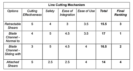
Decision Matrix for Selection of Line Cutting Mechanism
#4: Design Update 2: 10/7/2020
Some extremely important updates have come from our work the past couple of weeks. The first being an important meeting with Joe Zanetti, the man responsible for running the TCNJ Machine Shop. Having gained an abundant amount of experience in the manufacturing industry it was particularly intriguing for our group to hear some of the words of wisdom he had to offer. Specifically, Joe was able to express the importance of testing in the success of our project. Being that our project could one day be a consumer product it is important to gain as much feedback and data as possible, serving as a beacon of design direction. With Joe and Brian Wittreich offering expertise in injection molding and 3d printing, respectively, will play a huge role in the prototyping process we hope to start soon.
On the design front, the team has completed its subsystem design and has begun tinkering with numerous exterior body designs for the Vortex. Due to the nature of the design, it contains numerous rotating components. One of the questions we repeatedly ask ourselves is how we can enhance the support for these mechanisms. The gear train, specifically, is of utmost concern due to the problems which can arise as a result of the improperly meshed gears. While bearings are normally a reasonable design inclusion, spatial constraints make it difficult to include such items. Therefore the team is focusing on creating geometries which can serve as the means of support for the rotation components. Designing these built in supports will drastically reduce the number of components needed. Reducing the number of components is something that our advisor, Professor Sepahpour, has stressed repeatedly. One of the most important examples referenced has been the old fashioned pencil sharpener. The illustration below shows the intriguing parts of the design. The blade cylinders are connected to gears which not only mesh with each other, as well as ring gear, but they serve as means of alignment for each. This three gear system provides the support for each gear to mesh properly with the others. This type of “form” support is something that the Vortex would like to achieve.

Reference Image for old-fashioned pencil sharpener Design
#5: Interim Design Report: 10/30/20
The team is over the halfway point through SP-I. We have worked very hard up to this point, and have begun to reap the rewards of some of those benefits. While we were unable to fully print the first prototype by the time of the Interim Design Presentations, the printing will take place very soon. Most importantly, the team has designed the overall packaging of the subsystems and the components. Being that The Vortex is meant to be a hand held device it was important to understand the sizing which could “qualify” it as such. Statistical data as well as anthropometric data defines “average” size of human proportions. For example, for our case, hand size was important. Not only hand size, but grip breadth was of significant importance. This measurement is illustrated in the depiction below. For numerous tool manufacturers they use a reference value of 1.5 in. We used this value as a starting point and altered our dimensions depending on how we saw fit for the use and orientation of our device. This ensures that the majority of adults, most likely our primary consumers, are able to use the device comfortably.

Sample Anthropometric Measurement
In addition to the exterior of the device, internally, a compartment system has been designed, and was presented to the students and faculty within the Interim Design Presentation. The compartments serve two primary purposes. The first being that the compartments separate the cavity for line collection from the mechanical components. This allows for line to be collected without the risk of entanglement in the rotating mechanisms. The second purpose is to serve as the support, which was expressed in an earlier update. The orientation of these cavities, as well as the exterior provide the function of aligning the gears and encouraging proper meshing.This compartment structure is something that the team is pleased with, but believe that further improvement can be made.
Moving forward, the team is excitedly looking forward to the 3D printing of the first prototype. With a first prototype in hand, it will hopefully give the team their first hand on experience with what they have been working on. Due to the current COVID-19 climate, having hands on experience is more precious than ever. Therefore the team is looking forward to testing the device. After a comprehensive review the team will work to improve areas of weakness. The second design stage will focus primarily on incorporating the use of software tools for finite element and fatigue analysis. These validations of design will hopefully improve the robustness of the design immensely.
#6: Design Update 3: 11/18/2020
The team has successfully printed not 1, but 2, working prototypes. After printing the first, there were some physical characteristics of the device that we thought we could easily improve for a second iteration. Primarily, these were components that didn’t match up to proper anthropometric data. Certain components may have been just a little too small for the average fisherman to use comfortably. For example, the input handle to the device was quite small and proved to be difficult to use due to its dimensions. As for the mechanical and rotating components, the device worked quite soundly. Each of the rotating components was supported sufficiently, and operation was quite smooth. Currently, the prototypes are fully 3D printed. For the final product we are strongly considering the inclusion of a brass ring gear. Over time this brass gear would have a lubricating effect, enhancing the efficiency of itself and the meshed pinion. The self-lubricating effect would provide an enhanced life expectancy of the gears. This would also reduce the need of the consumer to apply lubrication themselves. Each of the components were also validated in their structural nature. This includes deformation, stress, and fatigue analysis on some of the critical components within the design. Depicted below are the stress and deformation plots of the line collection spool. It is important to note that these results are based upon the maximal loading cases, which will not be the standard operating conditions.

Deformation Plot for Spool

Stress Distribution Plot for Spool
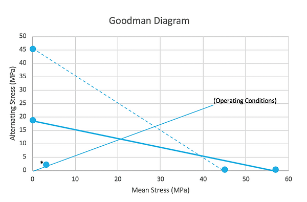
For some of the components it was also important to understand the effect of compounded loading over time. For these components fatigue analysis was conducted as a form of approval that the device could be used for a prolonged period of time. This is based on the fact that our device is a handheld device which can be used up to 4-5x week with 100s of rotations consistently enacted for line collection. The figure below depicts the Goodman Diagram for the input handle. The point in the lower left hand corner (*) marks the anticipated operating point. It is clear that the handle is safe and will handle the required long-term, structural demands of use.